Sostenuto pedal using Elk Pi hat

Hi all,

Let me take advantage of the “Elk Showcase” forum category and present you a little bit of the work I’m doing using the Elk Pi hat.

As some of you certainly know, I have researched sutainer / freeze / extrapolation / droning / call-them-what-you-like algorithms a bit last year, and eventually came up with a really simple and efficient time-domain algorithm for the task that works on all sorts of input signals (well, almost), guarantees no tonal coloration (on average) and produces non-static evolving output tones. I also wrote a scientific paper about it with the help of Dr. Leonardo Gabrielli from Università Politecnica dell Marche, Ancona, Italy, which was presented at the DAFx18 conference in Aveiro, Portugal, last year. Take a look at the paper if you wish: http://dafx2018.web.ua.pt/papers/DAFx2018_paper_11.pdf

The Elk guys contacted me a few months back and asked me if I wanted to make a prototype of some device using their upcoming Elk Pi hat, and making a guitar pedal out of this algorithm was the obvious choice for me. At the moment I’ve completed the software part and I believe the hardware side of affairs is mostly done too. In order to avoid forgetting about this journey and also to provide a nice log for whoever cares enough, I’ll post from time to time about the development process in this forum thread.

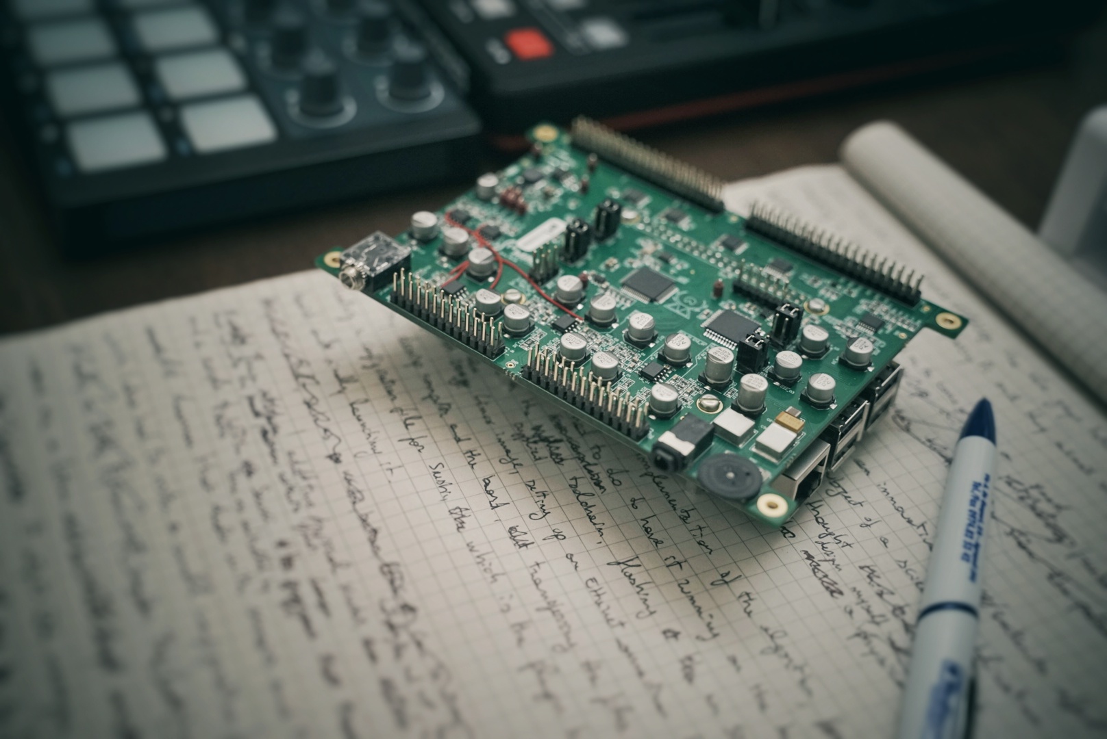
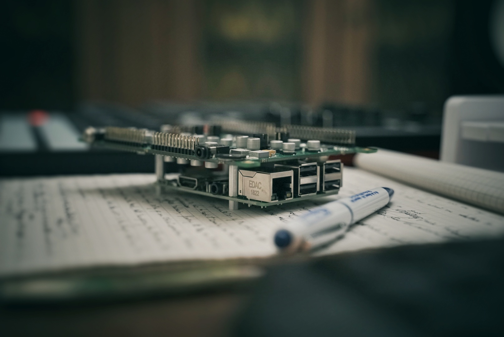
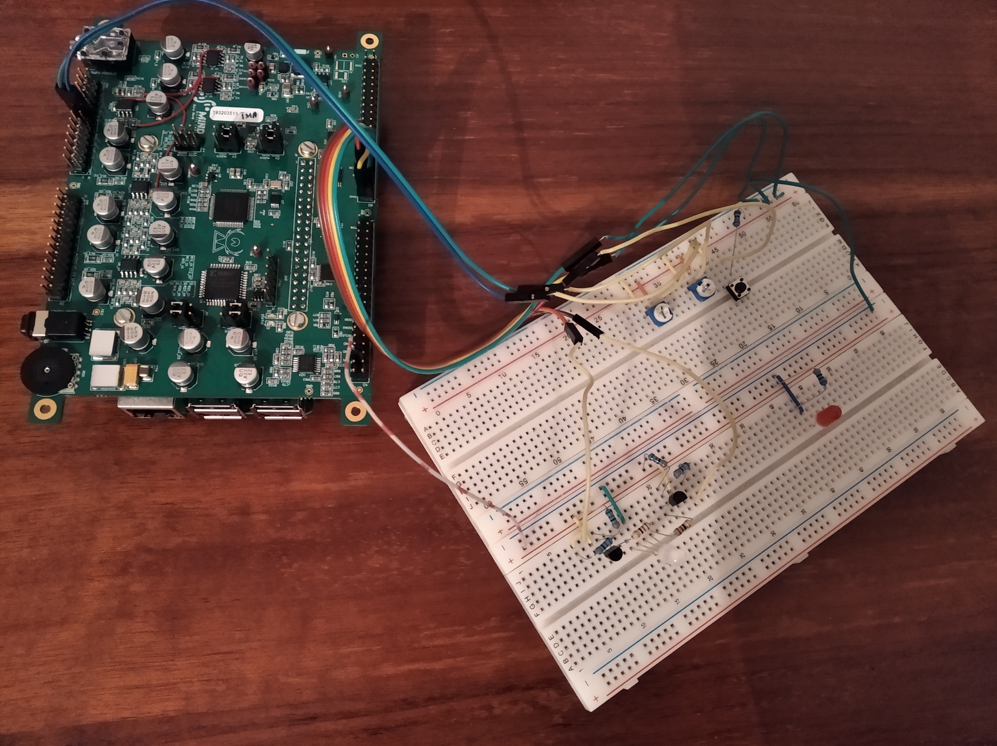
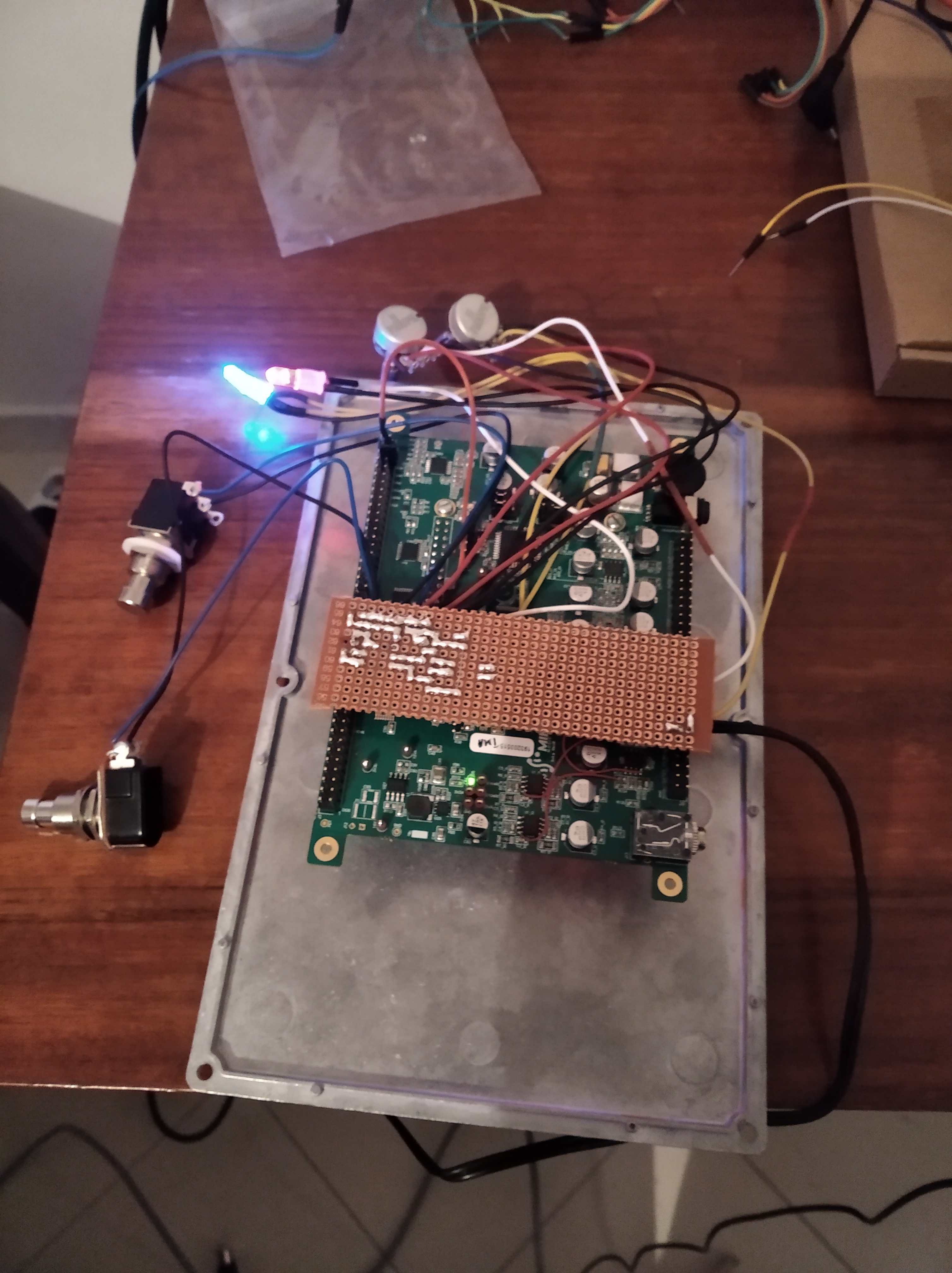
So, one morning I’ve received a shiny new Raspberry Pi 3, with power supply, SD card (that I soon discovered was broken), and Elk Pi hat board. Here’s the system assembled as per instructions that you can find now on github.


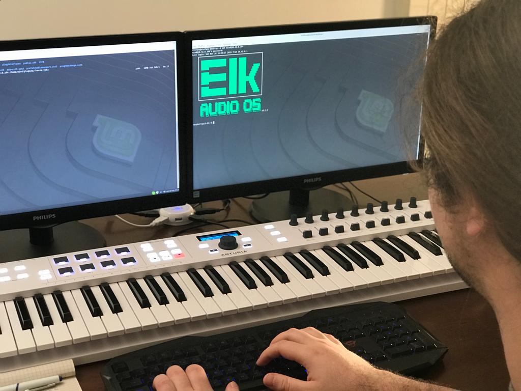
Once I had downloaded the Elk Audio OS image and flashed it on a working SD card, I could easily setup a shared Ethernet connection and login via SSH. The version of the image “at the time” (a few weeks ago) offered a standard login, but in the latest iterations there’s this nicer “textual logo”.

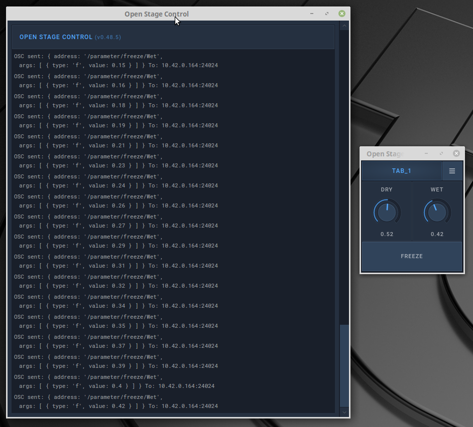
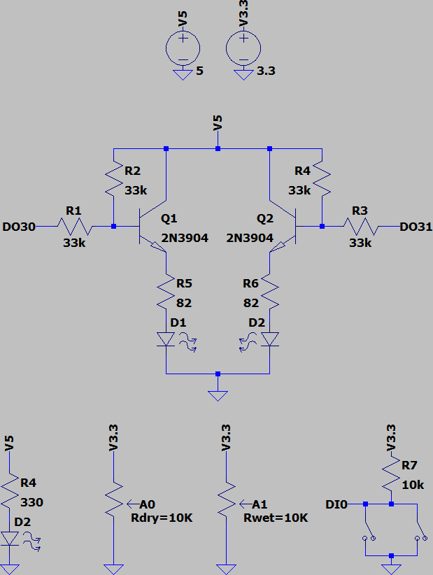
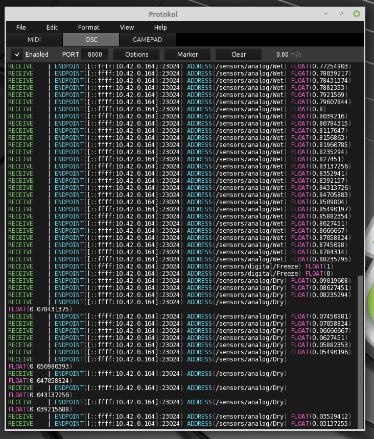
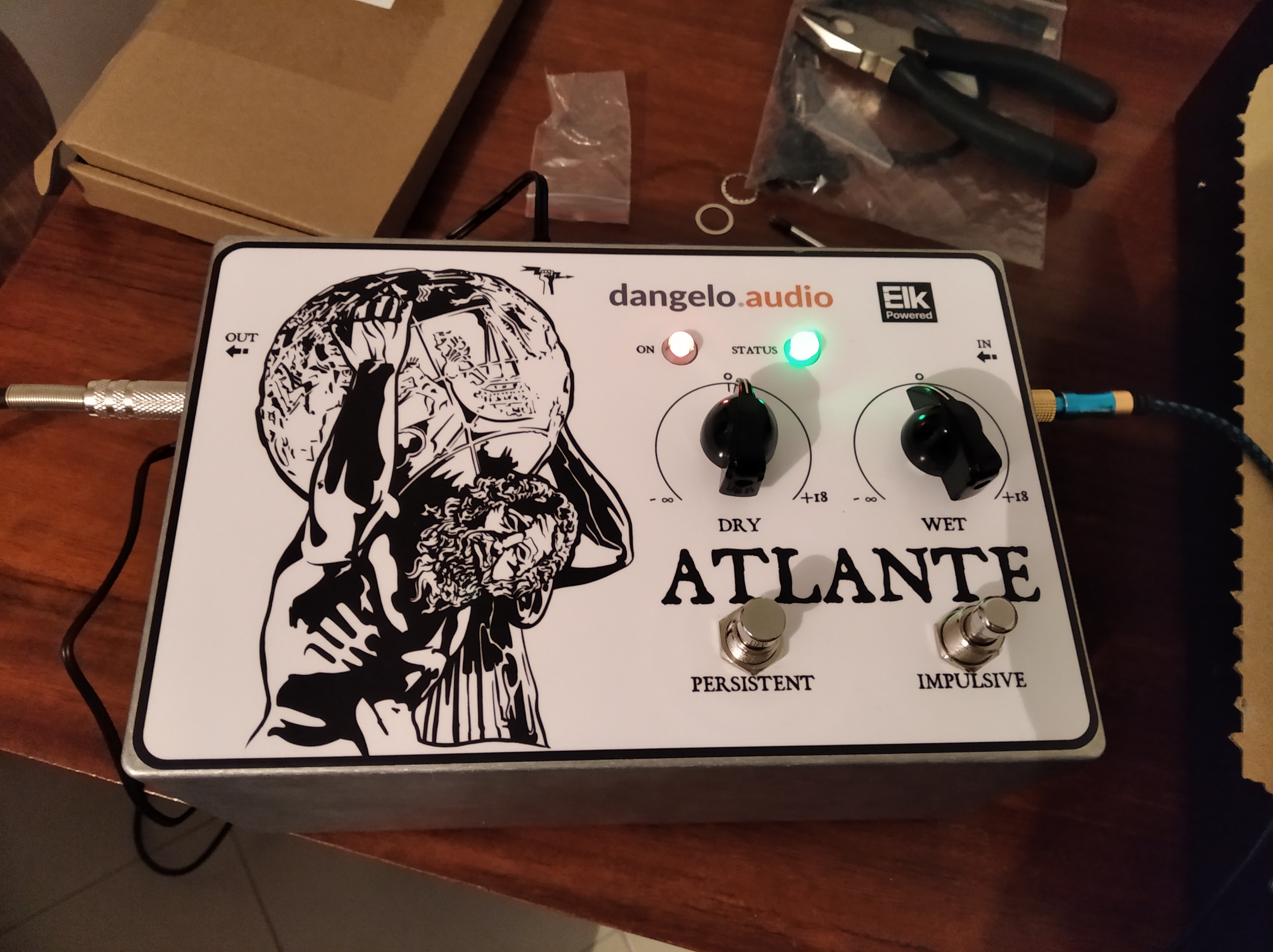
I already had the plugin written in VST3 format (without JUCE and the like, I started from the helloworld example in the VST SDK itself). It’s a pretty simple thing: you have two “continuous” parameters (dry and wet gains) and a “sustain” button that “stops” the sound. That’s all. Recompiling it for Elk was a breeze, I just needed to download the toolchain that the Elk guys gave me. The only minor “oddity” was that I also needed to apply a tiny patch (also supplied by them) to the VST SDK that allows for ARM64 builds - I’ve been assured that this it will be already included in the next official VST SDK version. I just used SSH to finally transfer files to the SD card without problems.

Next time I’ll talk about how I managed to run and control the plugin on the board.

10 Likes

Even though not strictly necessary, I kept consistency with the directory layout of the image w.r.t. plugins and configuration files, that is I created a freeze-vst3 folder inside /home/mind/plugins and put my freeze.vst3 bundle inside that, and I put all configuration files in /home/mind/config_files .

Ah, BTW, the “working name” of the project is “freeze” but I need to pick another one as there’s already a similar product with the same name on the market. I think that “sostenuto” would be a good one, but if you happen to have any ideas I’m all ears.

Now, in order to run Sushi, that is the plugin host, I wrote a rather trivial configuration file following the examples I found in the config_files directory itself and the Sushi documentation in the official github repo. Honestly, a little bit of guesswork was involved, but not much.

At first things didn’t work: I had segfaults using the RASPA backend and other errors using JACK and dummy backends. With a little bit of patience I found out that Sushi was trying to setActive() before setupProcessing(). Therefore I reported the bug – which is maybe fixed by now? – and added a simple couple-of-lines workaround in my code. That was the only time I ever touched the plugin source.

Another important note: while trying to find out what was the problem, I set the track mode to stereo in the configuration file and didn’t touch it ever since (the right channel is never going to be used and the CPU usage is low anyway, so… I will check when I have time :smiley:).

The plugin does almost nothing in its default state (it just lets the dry signal pass through), so at this point I could only check that indeed the signal was going through as expected when Sushi was running, which was the case. In order to “see it working” I used Open Stage Control, again as suggested in the official docs. I could create a small GUI in no time, yet IIRC in order to find out parameter names I had to look at the Sushi log file in /tmp/sushi.log.

Now the plugin was running and working as it should. Performance-wise these are the numbers I got (measuring as explained here):

  • an extremely stable 4.6/4.7% CPU usage when not “freezing”
  • a much less stable circa 13% on average and max 15.6% CPU usage when “freezing” – this was no surprise, the algorithm uses random (yet controlled) number of simultaneous “playback voices”

Keep in mind that this was an unoptimized debug build, and that on my main desktop PC the numbers are about 3%/8% (and with worse latency). Not bad, not bad at all! I am curious to know if anybody has other interesting performance measurements to show.

4 Likes

For the control I/Os, I decided to have:

  • one knob for each of the two continuous input parameters, that is one knob for the “dry” level and one for the “wet” level;
  • two switches controlling the “freeze” parameter, one of which is normally open and momentary and the other latched, so that you can either have the effect kick in only when actively pressing the momentary or use the latched switch to toggle the effect;
  • one red LED that just indicates the device is on, and an RGB led that is either green when the plugin is running but not freezing or blue when freezing (I couldn’t use just one RGB LED for reasons I will explain in the next post).

It’s mostly obvious how to do this given the information in the official datasheet. However, there are a couple of things I’m still wondering about, namely:

  • the maximum output current from digital I/Os is said to be 4 mA, but it is suggested that LEDs can be directly driven (with a series resistance of course) - I rather avoided this and used simple BJT LED drivers;
  • I seem to have digital input logic levels reversed - I don’t know if this is software- or hardware-related (BTW, the board I’m using should be a previous version w.r.t. the publicly available one), and it is not at all a big deal in practice, but still.

Long story short, this is what I came up with:

which I messily breadboarded in a few minutes like this:

To make sure that at least the inputs worked as expected, I wrote a configuration file for Sensei, the sensor and trasducer dameon, as explained here, and pointed its OSC backend to my desktop computer, so that I could intercept those messages using Protokol, like this:

5 Likes

Now that the plugin and the sensors worked, I had to enable communication between the two. I wrote a 50 lines Python script just for that using pyliblo and the Sushi gRPC control wrapper – in Elk jargon, I created the so-called “glue app”. It does:

  • connect to the local Sushi gRPC endpoint and query Sushi for parameter IDs (needed for sending commands to Sushi);
  • launch an OSC server for receiving Sensei output messages;
  • blink the status LED to indicate that the boot completed and set its color according to the current state;
  • listen and respond to OSC messages, namely:
    • when a dry or wet value change is received, ask Sushi to change the corresponding plugin parameter accordingly;
    • when a freeze value change is received, do the same and also set status LED color as needed.

Here you can see what the status LED does at the end of the boot and how it responds to pushing the freeze button (sorry, my mobile phone camera is not fantastic to say the least).

This was once again quite easy to accomplish and rather painless, yet there were a few minor inconveniences:

  • I had to look at the ADC workshop material to understand how to talk to Sensei from the glue app;
  • the status of digital outs during before Sensei takes control is unknown – this has forced me to have separate LEDs for on/off and status and have the status one blink after boot to indicate that now we’re in business;
  • I still didn’t find a way to get current sensor values from Sensei after boot – until then, the user has to touch all controls once at boot to make sure that the plugin parameter values match the real ones (at worst I’ll probably need to use “continuous mode”, but I’m happy if I can avoid it for a few reasons).

At this point I needed to “finalize” the project, which meant:

  • creating and enabling systemd services for Sushi, Sensei, and the glue app – an example was given in the Elk image for Sushi, and I just used that as a template, yet I had to change the working directory to a writable place for Sensei to run at all (but maybe this is not needed anymore?);
  • setting the root partition as read-only to avoid SD card corruption when pulling the plug – I just set the ro flag in /etc/fstab, but now there seem to be better ways.
1 Like

At this point only the actual “production” was left, and since I’m no expert in these matters, and I’m not particularly proud of the results (it’s been fun though), I’ll just post pics with a tiny bit of description of what I’ve done.

Here’s the metal enclosure with the drill mask on it. It’s been a nightmare to keep the holes centered with the horrible hand drill and clamps I have.

And indeed here’s the result while test fitting of panel components. It’s good enough but it looks better than it is.

For the electronics I built the LED driver circuit on perfboard and was clever enough to use the Elk board I/Os to hook it in a rather stable fashion – luckily the headers on the Elk board are spaced so that this is possible, .

And here’s the dark side of the perfboard. Again, I was lucky enough that there’s enough space vertically to have those few small components hanging down.

After checking that there were no shorts or other evident issues, I crossed fingers and plugged the power, and it just worked.

In the next episode I promise pedal name and artwork reveal. Maybe also sound reveal. Maybe before Christmas, maybe after… You better stay tuned!

2 Likes

Nice job. It looks clean in the pictures. What type of enclosure did you use?

Is it common to use transistors to drive led’s from a PI?

I would think you could get by with just a resistor to limit current?

What are the capacitors used for?

Nice job. It looks clean in the pictures. What type of enclosure did you use?

Thanks, I’m a total newbie. I used a Hammond 1550H.

Is it common to use transistors to drive led’s from a PI?

I would think you could get by with just a resistor to limit current?

I don’t know about the Pi, but the datasheet of the Elk board says it can output max 4 mA from the digital outs, and that IMO is not enough to make the LEDs bright enough.

What are the capacitors used for?

Which capacitors? I didn’t use any.

And finally, ladies and gentlemen, let me you introduce to you the Atlante pedal.

In case you wonder, Atlante is the Italian for Atlas, the Greek divinity that sustains the sky on his shoulders. The drawing is based off the so-called “Atlante Farnese” (or “Farnese Atlas” in English, I believe), which is located at the National Archaelogical Museum of Naples, and that also happens to contain the oldest known representation of the celestial sphere.

Sound reveal is coming next, certainly after new year’s eve. Keep staying tuned.

6 Likes

Hello and happy new year!

As promised, here’s some sound samples: https://soundcloud.com/user-884388289-540474067/sets/atlante-pedal-samples

And more juicy stuff is coming in the next days.

Anyway, I take the chance to point you to my website and to my freshly created Facebook page, but most importantly to draw some conclusions.

So far I’ve been tempted but at the same time kept myself at a safe distance from developing DSP for hardware products, even as a hobby, as there hasn’t been a general-purpose, usable, ready-made board at a reasonable cost on the market and making one yourself means investing a ton of time and money. In this regard, the Elk Pi Hat for me gets us software DSP developers much much closer to the physical world.

As expected there are still as of today a few rough edges and issues that could be tackled, but I don’t find real showstoppers. The worst offender so far for me was the undefined state of digital outs at boot, but hopefully it’s going to be fixed in a future board revision… or maybe not, since anyway you need to take these RPi-based boards for what they are, that is plyaground for experiments and prototyping, production is a different matter (Elk has you covered for that too anyway).

Documentation can be also improved somewhat, but still I could manage to do most of the work without bothering the Elk guys, and when I needed help they were more than helpful. And they follow this forum. Therefore, my advice is to hang around here and ask questions when you need information.

If you want to make a hardware prototype of anything that deals with sound, now you have very few excuses left.

5 Likes

And finally, here’s the long awaited restrospective + test and review video.

This concludes the project as far as I am concerned.

Again, this is my webiste and you can follow me on Facebook and Linkedin.

Thanks to Elk and thank you for your interest.

7 Likes

This looks fantastic! I met a guy from the tech world about 20’years ago that was a heavy hitter at Microsoft. His ‘side dream’ as he called it was a pedal just like this. I hope he finds himself here; he will go crunchy delicious!

For my part I’m gonna swim deeper into your flow on this creation,wish this was at the top of the heap when I was feeling my way around Elkland.

Til next time,

1 Like

Thanks, should you have any question feel free to ask.

Is the output from the Elk hat at line level? If so, did you have to make any changes to the signal to have safe operation with a guitar amp?

IIRC it was at line level or lower - in any case I didn’t have to add anything really.

1 Like

@sdangelo I’m kind of confused by the final prototype, because the input/output layout positions for the instrument cables (West and East) don’t line up with the orientation of the I/O on the elk hat (South and South). Did you have to use the blackboard in addition to the elk Pi Hat for the analog in/out, or am I missing something?

@keyth72 I’m working on a similar project - did going from guitar --> raspberry pi 3 --> amp end up causing any damage? Would you recommend this approach with the hifiberry again, or would you recommend using the Elk Pi Hat? I have a cheaper amp that I’m considering testing this on in case I damage something but thought maybe it’d be worth asking first.

Thanks in advance to both of you and thanks for your hard work and documentation on all of this. I’m not a hardware person and I’m trying to figure out which to use (Elk Pi Hat vs. HifiBerry) for building a pedal.

Hi @dvach. I took audio I/O on the board pins, see https://elk-audio.github.io/elk-docs/html/_images/image13.jpg, and run wires towards “stand-alone” TRS sockets (I drilled the chassis and used their nuts to place them there firmly).

Thanks for the explanation @sdangelo. Do you think that is something that a curious novice could do in a pinch? (I don’t have experience soldering.)

Soldering is not complicated, but I’d rather start with everything else. When you’re done in the worst case I bet you’ll find somebody helping you with enclosure and soldering. :wink:

that is the informative man I love it, thanks for sharing such info

1 Like